Finishing
This page lists the steps you might like to do next after completing your component.
Compile to CDCOM
Compile your XML component into the CDCOM binary format using the following command:
> circuit-diagram-cli component my_component.xml -o my_component.cdcom
Use in Circuit Diagram Desktop
To use either an XML or CDCOM format component in Circuit Diagram Desktop,
open Tools -> Components -> Components folder. Copy the component file
into the directory that opens and restart Circuit Diagram. You can add new
components to the toolbox by opening Tools -> Toolbox.
Circuit Diagram Desktop supports up to version 1.2 of the XML component format. To use newer XML versions, compile to CDCOM first.
Icons
To display icons in the toolbar in Circuit Diagram Desktop, the component must be compliled
to CDCOM format with icons embedded. This can be done by creating the appropriate 32px square PNG images
and then specifying the --resources argument when compiling. The image is used as an opacity mask so
it should have a transparent background.
To use an image called icon.png for all configurations of the component, specify --resources <component_name>_32.png ./path/to/actual_icon_file.png.
For example:
> circuit-diagram-cli component resistor.xml --resources resistor_32.png ./icon.png -o resistor.cdcom
To use a different icon for each configuration, multiple resources can be specified. You can see the list of expected icon names when compiling a component with verbose logging enabled:
> circuit-diagram-cli component resistor.xml -o resistor.cdcom --verbose
...
Icon resistor_32.png not found.
Icon resistor_64.png not found.
Icon resistor_resistor_iec_32.png not found.
Icon resistor_resistor_iec_64.png not found.
...
To specify multiple icons:
> circuit-diagram-cli \
    component resistor.xml \
    --resources resistor_32.png ./icon_1.png \
                resistor_64.png ./icon_2.png \
                resistor_resistor_iec_32.png ./icon_3.png \
    ...
    -o resistor.cdcom
To see the list of icons embedded in a CDCOM file, in Circuit Diagram Desktop, open
Tools -> Components, find the component and click Details. For high resolution
displays, Circuit Diagram supports 64px square icons, identified by
a _64.png suffix instead of _32.png.
Test in the Web Editor
Components can be tested directly in the Beta Web Editor using the local components feature. You will need to join the closed beta to use this.
First, compile the XML component to CDCOM format described at the top of this page.
In the components toolbox, click add more components.
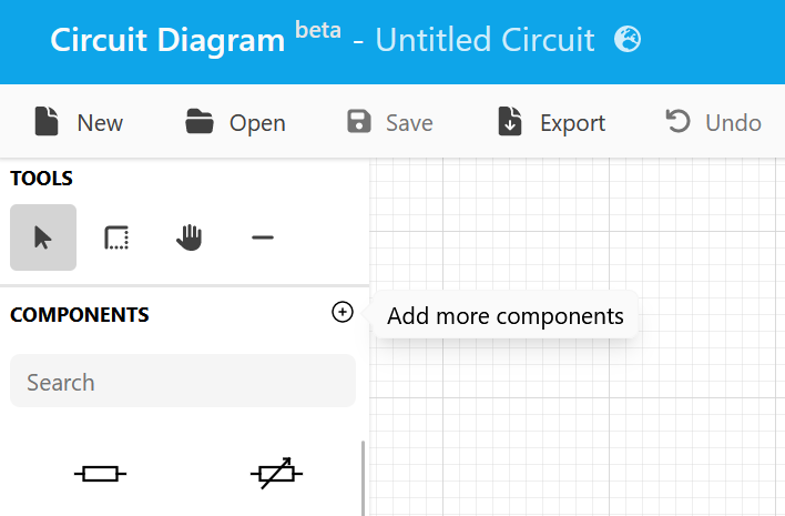
Select the local feed where you will be able to add up to three CDCOM format components.
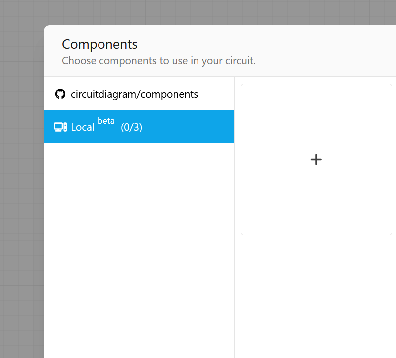
Close the dialog and your component will be shown at the end of the components toolbox.
This feature is intended for testing only. Using local components in a circuit will disable certain features in the Web Editor.
Publish to GitHub
Create a GitHub repository and commit your components.
You can explore components stored in any public GitHub repository using Component Explorer.