Basic Example
Before you start building components in more detail, this page explains how to build a basic component.
You can follow this page using either the VS Code Extension, or using the CLI directly.
Create a new file called my_component.xml and paste in the following XML:
<?xml version="1.0" encoding="utf-8"?>
<component version="1.5" xmlns="http://schemas.circuit-diagram.org/circuitDiagramDocument/2012/component/xml">
  <declaration>
    <meta name="name" value="My Component" />
    <meta name="minsize" value="50" />
    <meta name="author" value="Me" />
    <meta name="guid" value="8f764035-18c6-4421-ac7f-5cbd327d4e78" />
  </declaration>
  <connections>
    <connection start="_Start" end="_End" edge="both" />
  </connections>
  <render>
    <line start="_Start" end="_End" />
    <rect x="_Middle-10" y="_Middle-10" width="20" height="20" />
  </render>
</component>
This is our component file. To see what it looks like, we can render it to an image.
Option 1: VS Code Extension
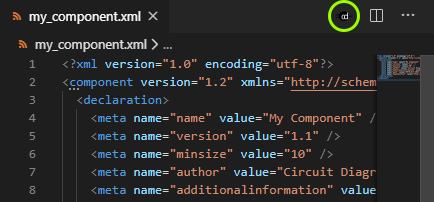
If you are using the VS Code extension, click the Circuit Diagram icon in the top right corner above the file.
This will render the component and open the image in a pane to the right.
Option 2: Command-line
If you want to use the command-line directly, run the following command:
> circuit-diagram-cli component my_component.xml -o render.png
Open the file render.png.
Rendered Component
You should see the following rendered image:

Continue to the next section to customise how the preview is rendered.