Circuit Netlists
Circuits created using the Web Editor can now be viewed or exported as a circuit netlist.
Netists describe how components in a circuit are connected together, and are commonly used for circuit analysis, simulation and PCB design.
The circuit details page also shows a rendered view of the circuit with each of the netlist nodes marked on the circuit visually.
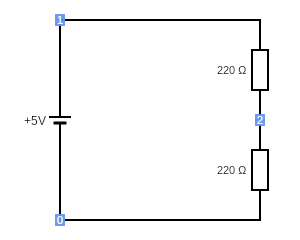
The above circuit is represented by the following netlist:
V1 1 0 5
R2 2 0 220
R3 1 2 220
The first line describes a Voltage source between nodes 0 and 1 with a voltage of 5 volts.
The second line describes a Resistor between nodes 0 and 2 with a resistance of 220 ohms. The third line describes a second resistor.
You can match up the number of each node with the node indicators (the blue boxes) on the rendered version of the circuit.
View the circuit page for this example circuit to find out more.